
1. Introduction
The SoniShield Duo™ Room Conditions Monitoring System provides continuous monitoring of environmental conditions including:
- Ambient Temperature
- Relative Humidity
- Differential Pressure
Proper installation and sensor placement are essential to ensure accurate, reliable monitoring.
This guide provides recommended installation practices for regulated environments including compounding pharmacies, cleanrooms, healthcare facilities, and other controlled environments.
Final sensor locations should be reviewed against:
- Facility environmental monitoring plans
- HVAC balancing documentation
- Room certification reports
- Site-specific requirements
2. Required Tools & Materials
Pre-Installation
- Flat-head screwdriver
- Phillips screwdriver
- Drywall saw
- Fish tape
- Wire cutters
- Wall anchors and screws
- Single-gang box/bracket (optional)
- 7" zip ties
- 1" zip tie mounting squares
Installation
- Mobile device with SoniCloud Mobile App
- Wire cutters
- Zip ties
- Mounting Squares
3. Sensor Placement Requirements
3.1 Temperature & Humidity (HT) Sensor Placement
The HT sensor should be installed in a location representative of the room environment.
Recommended Location
Install the HT sensor:
- 48–72 inches above finished floor
- On an interior wall whenever possible
- In the general working area of the room
- In an area with free airflow around the sensor
Avoid Installing HT Sensors:
Do not install:
- Directly below supply air diffusers
- Near return air grilles
- Near doors or pass-through chambers
- In direct sunlight
- Above heat-producing equipment
- Behind shelving, cabinets, or equipment
- In stagnant airflow areas
3.2 Differential Pressure Pickup Plate Placement
Differential pressure pickup plates measure the pressure relationship between adjacent rooms.
For accurate pressure monitoring:
- Install pickup plates on the actual pressure boundary
- Install both pickup plates at approximately the same height on connecting walls
- Preferred mounting height:
- 48–72 inches above finished floor
Recommended Clearance
Maintain:
- Minimum 5 feet from supply air diffusers
- Minimum 3 feet from return air grilles
- Minimum 3 feet from doors or openings
Preferred Installation
Wall mounting is preferred.
Ceiling mounting should only be used when required by site conditions and should avoid direct airflow patterns.
4. Differential Pressure Examples
Positive Pressure Room
Example: Non-Hazardous Buffer Room
Ante Room | Compounding Room (+ Positive Pressure)
DPS/HT Dual Plate | WALL | DPS/HT Dual Plate
Reference | Monitored Room
Negative Pressure Room
Example: Hazardous Drug Buffer Room (- Negative Pressure)
Ante Room | HD Compounding Room
DPS/HT Dual Plate | WALL | DPS/HT Dual Plate
Reference | Monitored Room
5. DPS Tubing Installation Requirements
For reliable pressure monitoring:
- Route tubing directly whenever possible
- Avoid unnecessary tubing length
- Do not coil excess tubing
- Avoid sharp bends
- Prevent tubing from being pinched or compressed
- Protect tubing from mechanical damage
- Avoid areas where condensation may collect
Verify tubing is fully seated on all barb fittings.
6. Pre-Installation Instructions
Before installing the SoniShield Duo:
- Confirm power is available at the Duo installation location.
- Verify sensor locations meet placement requirements.
- Confirm tubing and sensor cable pathways.
The pre-installation kit includes:
- Differential pressure pickup plates
- DPS tubing
- HT sensor cables
- Additional accessories as ordered
The pre-installation process must be completed before Duo installation.
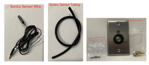
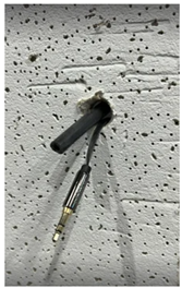
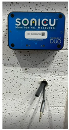
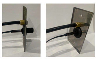
7. Differential Pressure & HT Dual Pickup Plate Installation
Option 1: Single-Gang Box/Bracket Installation
- Determine optimal location in the room to be monitored.
- Install the single-gang box/bracket flush with the finished wall.
- Route through the wall from the location of the single gang box to where the Duo meter will be placed:
- DPS tubing
- Male end of the HT sensor cable (The female end of the HT sensor cable should remain in the single gang box)
- Install the filter and barb fitting on the pickup plate.
- Connect DPS tubing to the barb fitting on back of the pickup plate.
- Ensure tubing fully covers the barb fitting.
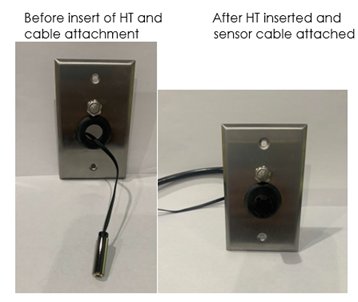
- Pull HT extension cable through the grommet of the pickup plate.
- Secure the pickup plate to the gang box/bracket using the included screws, leaving the sensor cable on the outside of the plate.
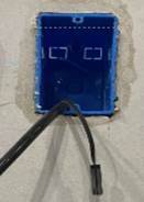
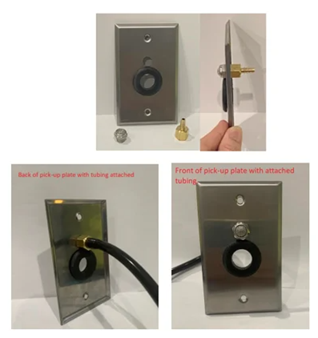
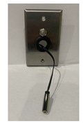
Option 2: Direct Wall Installation
- Identify approved pickup location.
- Drill access opening.
- Route tubing and sensor cable.
- Install filter and barb fitting.
- Connect DPS tubing.
- Pull HT cable through grommet.
- Secure pickup plate.
8. HT Sensor Installation
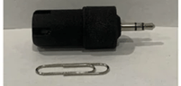
- Connect the HT sensor to the sensor cable that is inside of the single gang box.
- Insert the HT sensor so it sits snuggly into the pickup plate grommet.
- Confirm the sensor is exposed to room air.
- Ensure the sensor is not blocked by equipment or furnishings.
9. Duo Meter Installation
The Duo meter should:
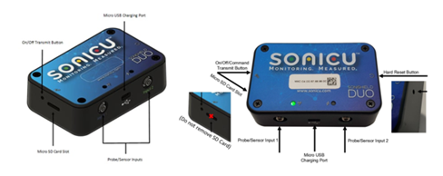
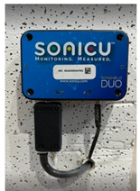
- Be mounted securely with the provided double sided tape by removing the red-colored adhesive backing on the back of the meter. Clean the surface where the meter is going to be placed. Press the meter firmly to ensure full adhesion.
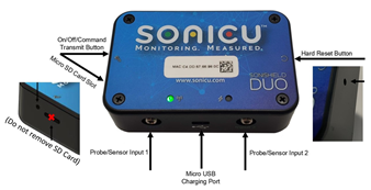
- Be plugged in using the supplied micro-USB power cable and adapter into the bottom of the Duo meter and into a nearby wall outlet.
- Remain accessible
- Be protected from damage
- Be located in a stable indoor environment
Where required by facility standards, mechanical mounting or a Duo mounting bracket may be purchased instead of the pre-added adhesive mounting.
Note: The Duo meter will operate on battery power only if required. Additional steps should be recorded in your SOP to check battery life and charge when needed.
10. HT & DPS Sensor Installation
The HT sensor should:
- Already be installed in the room being monitored
- The male end of the HT extension cable should be plugged into one of the inputs on the bottom of the Duo meter
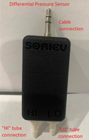
- Plug the DPS sensor directly into the other input on the bottom of the Duo meter
- Be located in the reference room which is outside the monitored room
- Remain accessible for calibration and service
The DPS sensor should:
Connect DPS tubing:
Connect the tubing that is coming through the pickup plate or wall onto the barb marked HI on the DPS sensor. Ensure tubing is pushed down completely over the inlet barbs.
The barb marked LO on the DPS sensor should be left open to receive the air from the reference room.
Verify:
- Tubing is fully seated
- Tubing is not restricted
The DPS system measures the pressure difference between the monitored space and the reference space.
The pickup plate location is more critical than the DPS sensor location.
11. Duo & Sensor Activation
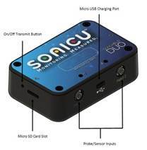
Power the Duo Meter On
- Press and hold the On/Off Transmit button with the included reset pin.
- Wait for green LED indication flash then release the On/Off Transmit button.
- Allow meter startup sequences inclusive of flashing LEDs.
- The meter is ready to activate to SoniCloud when you see a solid green LED on the Duo meter.
WiFi devices: If your device was preprogrammed by Sonicu, your device should now connect to your WiFi network.
SoniLink: If your device is SoniLink it will connect to your SoniLink Hub which should already be installed in a centralized location of the Duo meters.
12. SoniCloud Connectivity
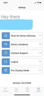
- Open SoniCloud Mobile App and login using your email and password previously created. If you do not have the mobile app, scan the QR code.
- Select:

Settings → Scan for Sonicu Devices
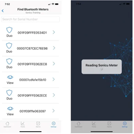
- Select the appropriate Duo by serial number.
13. DPS Field Calibration
To ensure correct pressure readings, zero the DPS sensor before activation:
- Remove tubing from the DPS HI port.
- From the mobile app select:
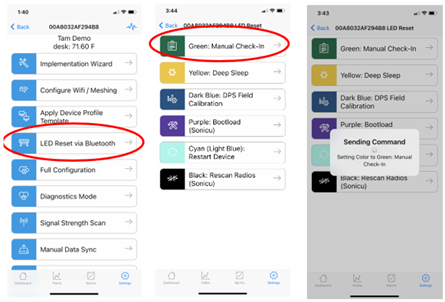
LED Reset via Bluetooth → DPS Field Calibration
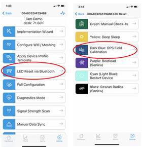
- Wait approximately one minute for the air pressure to reach 0 in the tubing.
- Reconnect tubing to the DPS HI barb.
- Click “Back” to return to the previous option page.
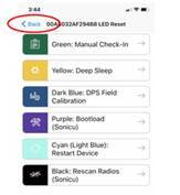
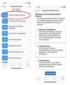
- Select Implementation Wizard
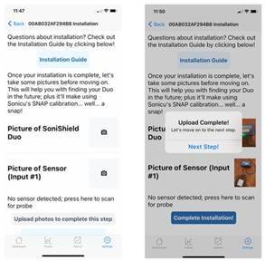
- Click “Get Started” and follow the steps to take pictures of the Duo meter, installed sensors, and pickup plates.
- Click “Upload Photos”. The photos will upload and display “Upload Complete” when the photos are uploaded.
- Click “Next Step”
- Your Duo meter should automatically connect if it is connected to either WiFi or the SoniLink Hub. The meter will move through Establishing Connectivity to Connected. If it does not connect, see step 13.
- Click “Next Step”
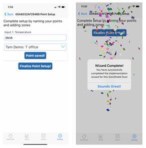
- Complete the setup by naming your points and adding them to the correctly named zones.
- Differentiate your point names by referencing the room, point type (Positive Pressure, Negative Pressure, Temperature, or Humidity)
- Point names should be something your staff is familiar with (ex: Positive Pressure - Compounding Room 1)
- If you have multiple locations, it is beneficial to include the location name before the point name to differentiate between locations during alarm notifications (ex: Indianapolis – Positive Pressure - Compounding Room 1)
- Select the Zone this point will be located in on the SoniCloud dashboard be selecting the down arrow and choosing the Zone.
- If both inputs are being used on the Duo and are monitoring pressure, temperature, and humidity, there will be 3 points to name.
- Positive or Negative Pressure
- Temperature
- Humidity
- Click “Save Point” and “Finalize Point Setup”
- Once each meter is activated on SoniCloud, you will receive some confetti and the Wizard Complete notification.
- Click “Sounds Great!”
- Continue this activation process for all Duo meters and sensors.
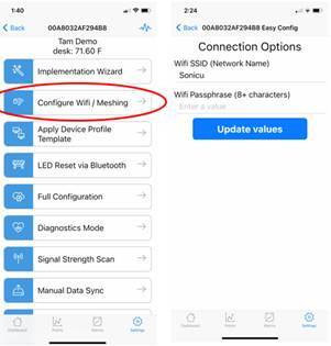
- If the Duo meter is not connected, either the network information was not provided to Sonicu for pre-programming or another issue has occurred. Duo meters must be configured with the customers’ WiFi SSID & Passkey, or the SoniLink Hub must be installed prior to installation.
- Return to the main Settings page on the Mobile app.
- Click “Configure WiFi/Meshing”
- Add the WiFi SSID & passphrase settings
- Click “Update values”
- Once the SSID and Passphrase have been updated, return to the Implementation Wizard to complete the activation of your Duo meters to SoniCloud.
- Additional troubleshooting:
- If you have many meters that need to be activated, Sonicu can update your SoniCloud site with a Device Profile Template that includes our network settings to make activating your WiFi settings.
- Please contact support for further information.
14. Installation Verification
Before completing installation verify:
☐ HT sensor location approved & installed
☐ DPS pickup plate locations approved & installed
☐ Tubing installed without restrictions
☐ Tubing connections secure
☐ DPS zero calibration completed
☐ Pressure direction verified
☐ Positive rooms show positive pressure
☐ Negative rooms show negative pressure
☐ Device connected to SoniCloud
☐ Calibration documentation retained
15. Common Installation Errors
Avoid:
❌ HT sensor directly under HVAC supply
❌ DPS plate near doors
❌ DPS plate near return grilles
❌ DPS plate in turbulent airflow
❌ Excess tubing coils
❌ Blocked HT sensors
❌ Incorrect pressure reference
16. Troubleshooting
If the Duo does not connect:
- Perform a Green LED Reset from your SoniCloud Mobile app.
- Run diagnostics through the SoniCloud Mobile App.
- Select “Settings” on the bottom right corner.
- Select “Scan for Sonicu Devices”
- Find the meter you want to diagnose and select the meter.
- Select “Diagnostics Mode” then “Start Diagnostics”
- Wait about 3 minutes until the on-screen prompt indicates “Diagnostics Complete”. Click Ok. Note: You must be within Bluetooth range of the meter to complete diagnostics
- Record device serial number.
- Notify technical support of the issue. Please include the SoniCloud site URL, customer name, and meter serial number in your request.
Technical Support
Email: support@sonicu.com
Phone: 317-468-2345
Hours:
Monday–Friday
8:00 AM–5:00 PM EST