
The SoniShield View location can vary by application but is typically located on the outside of the room being monitored next to the door to be easily viewed prior to entering.
Below is an example of a finished installed pre-install kit and meter, your application may vary.

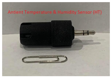
Installation of your Ambient Temperature & Humidity (HT) Sensor Instructions
1. Locate your HT sensor.
2. Install the HT sensor at the pick-up location. If the pick-up plate is already attached to the wall, insert the sensor cable, which should be hanging out through the rubber grommet, into the HT sensor. Push the large end of the HT sensor into the rubber grommet on the pick-up plate.
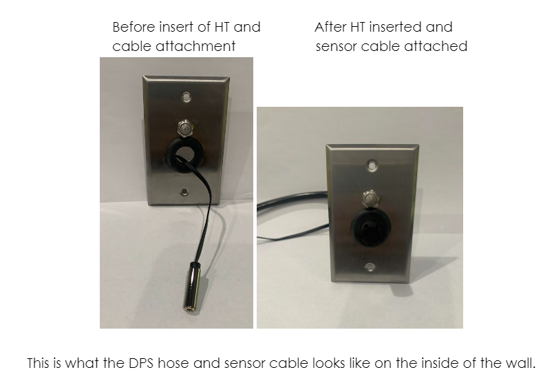

3. If the pick-plate is not already attached to the wall, screw the pick-up plate to the wall with the included screws after installing the HT sensor.


4. This completes the installation of the pick-up and HT sensor.
Installation of your SoniShield View Instructions


1. Confirm power is 24V DC with multimeter before starting installation of the SoniShield View. IF 24V DC POWER HAS NOT BEEN CONFIRMED, DO NOT PROCEED AND VERIFY CORRECT POWER. USING HIGHER VOLTAGE POWER WILL DESTROY THE HARDWARE AND MAKE IT UNUSABLE.

2. Plug the supplied power into the device. It can only be installed one way to avoid any confusion.

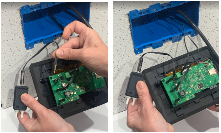
3. Plug the HT sensor cable from the 3-gang box into one of the 3.5 mm View inputs on the left side of the meter.

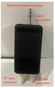
4. Plug the female end of the included short 6-inch cable onto the DPS sensor. Then plug the male end of the DPS cable to one of the 3.5mm inputs on the left side of the View. This extension cable will give the sensor room to fit inside the 3-gang box.


5. Connect the included short piece (~6”) of DPS tubing to the DPS tubing connector barb on the left Housing side of the View.


6. Connect the other end of the DPS tubing to either the HI or LO input on the DPS sensor (see below for directions on which input to select). The Differential Pressure Sensor should be located in a DIFFERENT room than the Air Pressure Pickup, Two examples follow:
Option 1: If the DPS SENSOR is located in the room being monitored for air pressure, install the PICKUP in an unpressurized room right outside. Connect the tubing from the pickup to the DPS sensor on inlet port marked “LO”.
Option 2: If the DPS SENSOR is not located in the room being monitored for air pressure, put the PICKUP in the room being monitored for air pressure and connect the tubing from the pickup to the DPS sensor on inlet port marked “HI”.

7. Plug the View tubing from the 3-gang box into DPS sensor.

8. Gently remove the Faceplate from the Housing for final installation of the View into the 3-gang box. Remember the short DPS tube should still be attached to the Housing.

9. Carefully slide the SoniShield View into the 3-gang box, holding in place while installing all included 4 mounting screws.
10. Once Installation is complete, please continue with the setup of your SoniShield View steps found in the SoniShield View Activation and Quick Start Guide.
*PLEASE NOTE*
1. The mounting tabs should be touching the wall when installing the View.
2. DO NOT overtighten mounting screws as this may cause damage to the View.
3. DO NOT pinch sensor cables or tubing during the View mounting.
4. Confirm the reset button is not in contact with the side of the 3-gang work box. The reset button is on the right side of the View.
If any questions arise during your pre-install, please contact Sonicu Support for assistance. Sonicu Support can be reached by email at support@sonicu.com or by calling (317) 468-2345. Sonicu Support is available M-F 8 am-5 PM EST.