Temperature/Humidity (HT) & Differential Pressure (DPS)
Pre-Installation, Installation & Placement Guide with Mobile App Activation
Application: Healthcare, Compounding Pharmacy, USP <797>/<800> Environmental Monitoring Applications
1. Introduction
The SoniShield View™ Room Conditions Monitoring System provides continuous local display and monitoring of ambient temperature, relative humidity, and differential pressure.
The View displays real-time readings locally and transmits data to SoniCloud for alarming, reporting, and long-term data storage. Proper installation, placement, tubing routing, and configuration are essential for accurate monitoring.
Final installation locations should be reviewed against:
• Facility environmental monitoring plans
• HVAC balancing documentation
• Room certification reports
• Site-specific requirements
2. Required Tools & Materials
Pre-Installation
• Flat-head screwdriver
• Phillips screwdriver
• Drywall saw
• Fish tape
• Flush cutters or wire cutters
• 7" black zip ties
• 1" black zip tie mounting squares
• 3-gang in-wall or surface-mount box, if not supplied by Sonicu
• Single-gang box or low-voltage bracket, optional
• Multimeter
Installation
• Mobile device with the SoniCloud Mobile App
• Phillips screwdriver
• Multimeter
• SoniShield View
• 24 VDC power connector
• HT sensor and extension cable
• Differential Pressure Sensor and short extension cable, if applicable
• DPS tubing and pickup plate, if applicable
3. View, Sensor & Pickup Plate Placement
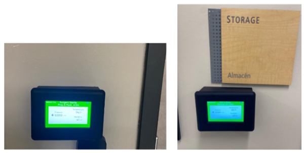
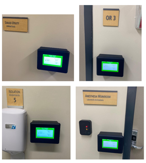
The SoniShield View is typically installed outside the monitored room near the door so the display can be viewed before entering. The final location may vary by application.
• Select a location that is easy to view and access.
• Confirm the location can accommodate a 3-gang in-wall or surface-mount box.
• Confirm 24V DC power can be routed to the View.
• Select HT sensor and differential pressure pickup locations.
• Plan cable and tubing routes before cutting or drilling.
Recommended HT & DPS Sensor & Pick Up Plate Location
- 48–72 inches above finished floor
- On an interior wall whenever possible
- In the general working area of the room
- In an area with free airflow around the sensor
For reliable pressure monitoring:
- Route tubing directly whenever possible
- Avoid unnecessary tubing length
- Do not coil excess tubing
- Avoid sharp bends
- Prevent tubing from being pinched or compressed
- Protect tubing from mechanical damage
- Avoid areas where condensation may collect
Avoid Installing HT Sensors:
- Directly below supply air diffusers
- Near return air grilles
- Near doors or pass-through chambers
- Wall mounting is preferred.
- Ceiling mounting should only be used when required by site conditions and should avoid direct airflow patterns.
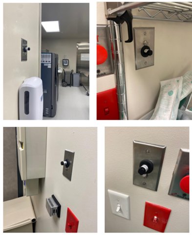
Preferred Installation
4. Pre-Installation Requirements
1. Confirm 24V DC at 0.5 A power has been routed to each View location and verify voltage with a multimeter.
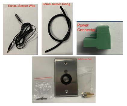
2. Confirm the pre-install kit is complete, including pickup plates, sensor cables, DPS tubing, the two-conductor power connector, and ordered accessories.
3. Confirm the View location, pickup locations, and cable and tubing routes.
4. Confirm the required 3-gang in-wall or surface-mount box is installed.
5. Complete the pre-installation work before installing the SoniShield View.
Important: Do not connect the View until 24 VDC power has been verified. Higher voltage can permanently damage the hardware.
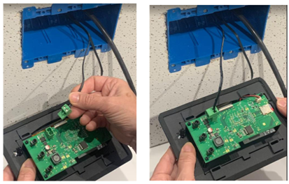
5. SoniShield View Mounting Box Pre-Installation
In-Wall Mounting
1. Confirm sufficient sensor cable and DPS tubing to reach from the 3-gang box to the pickup locations.
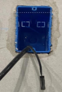
2. Install the 3-gang work box level and flush with the finished wall.
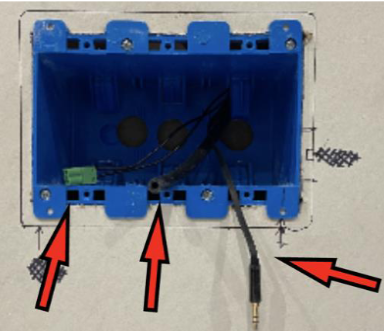
3. Route the male end of the HT sensor cable and the required DPS tubing into the 3-gang box.
4. Identify the HT sensor and DPS pickup locations and the cable and tubing paths.
5. Route the female end of the HT sensor cable and one DPS tube through the wall or ceiling to the pickup location.
6. Route 24 VDC power with the attached two-conductor connector into the 3-gang box.
Surface-Mount Installation
• Use a 3-gang surface-mount box when wall depth does not allow an in-wall box.
• Use surface mounting for non-permanent or less invasive installations.
• Route the power connector, sensor cable, and DPS tubing into the surface-mount box.
• Verify the box is securely mounted and level.
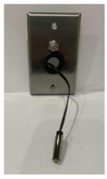
6. Pickup Plate & DPS Tubing Installation
Option 1: Single-Gang Box or Low-Voltage Bracket
1. Confirm sufficient tubing and sensor cable length between the pickup location and the View location.
2. Install the single-gang box or bracket level and flush with the finished wall.
3. Route the female end of the HT sensor cable and one DPS tube into the box or bracket.
4. Keep the male end of the HT sensor cable and remaining DPS tubing at the View location.
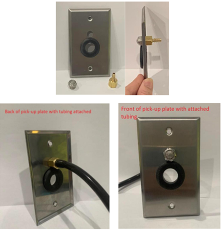
5. Push the filter through the pickup plate.
6. Thread the barb fitting onto the back of the filter.
7. Connect the DPS tubing to the barb fitting and ensure the tubing fully covers the barb.
8. Pull enough HT sensor cable through the pickup plate grommet for sensor installation.
9. Secure the pickup plate to the box or bracket with the included screws.
Option 2: Direct Wall Installation
1. Identify the approved pickup location and cable and tubing route.
2. Drill an approximately 1.5-inch access opening at the pickup location.
3. Retrieve the HT sensor cable and DPS tubing routed from the View location.
4. Keep the male end of the HT cable and remaining tubing at the 3-gang View box.
5. Push the filter through the pickup plate.
6. Thread the barb fitting onto the back of the filter.
7. Connect the DPS tubing and ensure it fully covers the barb.
8. Pull the HT cable through the pickup plate grommet.
9. Secure the pickup plate to the wall using the included screws.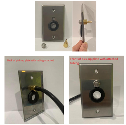
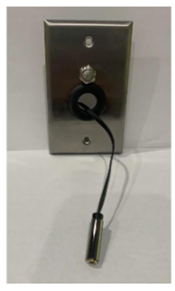
7. HT Sensor Installation
1. At the pickup location, connect the HT sensor to the sensor cable.
2. Insert the large end of the HT sensor into the pickup plate grommet so it fits securely.
3. If the pickup plate is not already mounted, secure it to the wall after connecting the sensor.
4. Confirm the sensor is exposed to room air and is not blocked by furniture, shelving, or equipment.


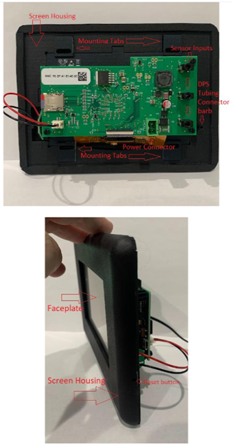
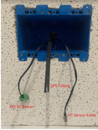
8. SoniShield View Hardware Identification
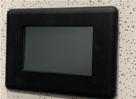
• Screen housing and removable faceplate
• Mounting tabs
• Sensor inputs
• DPS tubing connector barb
• Power connector
• Reset button
9. SoniShield View Installation
1. Verify incoming power is 24V DC with a multimeter. Do not proceed until correct voltage is confirmed. Using Higher Voltage Power will destroy the View hardware and make it unusable and void the warranty.
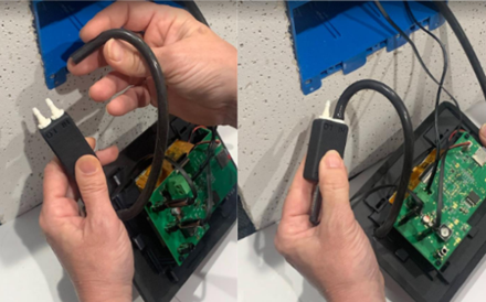
2. Connect the supplied power connector to the View. The connector is keyed and can be installed only one way.
3. Connect the HT sensor cable from the 3-gang box to one of the 3.5 mm sensor inputs on the View.
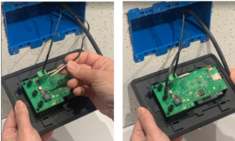
4. Connect the female end of the short six-inch extension cable to the DPS sensor. Connect the male end to an available 3.5 mm input on the View.
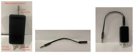
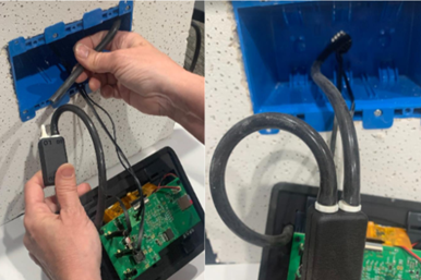
5. Connect the included short piece of DPS tubing to the DPS tubing connector barb on the View housing.
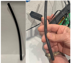
6. Connect the other end of the short tubing to the LO port on the DPS sensor.
7. Connect the DPS tubing routed from the pickup plate to the remaining DPS sensor port as required by the application.
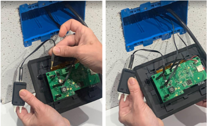
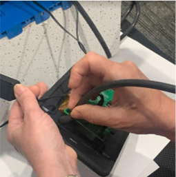
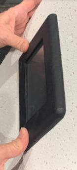
8. Gently remove the faceplate from the View housing. Keep the short DPS tube connected to the housing.
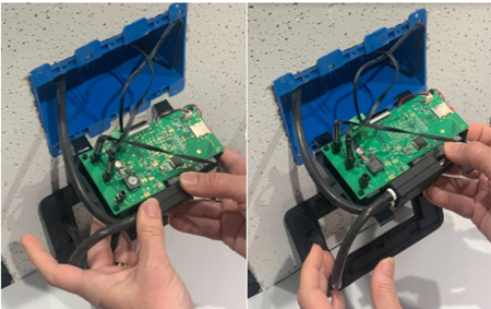
9. Carefully place the DPS sensor, cables, and tubing inside the 3-gang box.
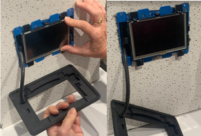
10. Slide the View into the box and install all four mounting screws. Confirm the mounting tabs contact the wall.
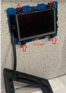
11. Reinstall the faceplate.
Important: Do not overtighten mounting screws, pinch cables or tubing, or allow the reset button to contact the side of the box.
10. Differential Pressure Connections
The Differential Pressure Sensor must be located in a different room than the air pressure pickup.
Positive Pressure Room
• Install the pickup in the positively pressurized monitored room.
• Install the DPS sensor in the unpressurized or reference room outside the monitored room.
• Connect the pickup tubing to the correct HI/LO port for the installation.
Negative Pressure Room
• Install the pickup in the negatively pressurized monitored room.
• Install the DPS sensor in the pressurized or reference room outside the monitored room.
• Connect the pickup tubing to the correct HI/LO port for the installation.
Verification: After installation, confirm the displayed pressure direction matches the certified room pressure relationship.
11. Power-On & Physical Installation Verification
1. Confirm the View powers on.
2. Confirm the display shows values from all installed sensors.
3. Confirm all sensor connections are fully seated.
4. Confirm DPS tubing completely covers all barb fittings.
5. Confirm tubing is not pinched, kinked, or restricted.
6. Confirm the faceplate is securely installed.
12. SoniCloud Mobile App Connection
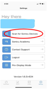
1. Open the SoniCloud Mobile App and sign in with your SoniCloud credentials.

2. From Settings, select "Scan for Sonicu Devices."
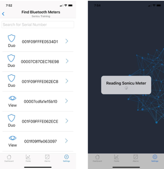
3. Locate the View by searching for the last four characters of the serial number or by scrolling through nearby devices.
4. Select the correct View and allow the app to read the device configuration.
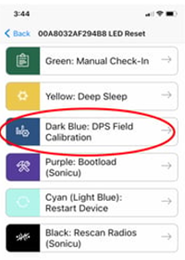
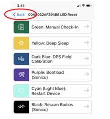
13. DPS Field Calibration
1. Record the existing tubing connections before disconnecting any tubing.
2. Remove the tubing from the DPS sensor so both ports are exposed to the same room pressure.
3. Open the SoniCloud Mobile App and select the View.
4. Select "LED Reset via Bluetooth."
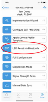
5. Select "DPS Field Calibration."
6. Wait approximately one minute for the pressure to stabilize at zero.
7. Reconnect the tubing to the same ports recorded before calibration.
8. Verify the differential pressure reading and direction.
9. Return to the Implementation Wizard.
14. Implementation Wizard & Connectivity
1. Select "Implementation Wizard" when network information was provided to Sonicu before shipment.
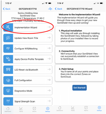
2. Select "Get Started" and follow the prompts.
3. Take the required pictures of the View, sensors, and pickup plates.
4. Upload the installation photos and confirm the upload completes.
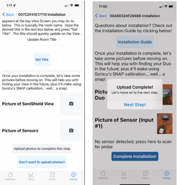
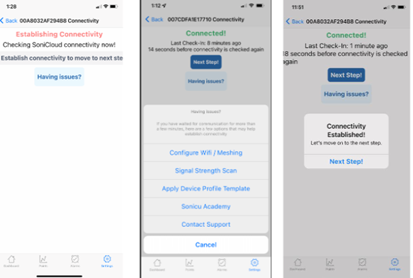
5. Continue to the connectivity step.
6. Confirm the View changes from Establishing Connectivity to Connected.
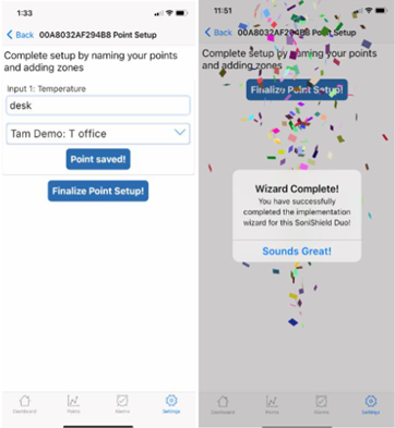
7. Continue to point setup.
8. Name each point using a clear location and point type.
9. Assign each point to the correct SoniCloud zone.
10. Save and finalize each point.
11. Repeat the process for all Views and sensors.
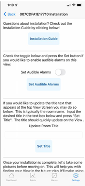
15. View Display Configuration
Use the SoniCloud Mobile App to configure:
• Display title text
• Point thresholds
• Audible alarms or buzzers
• Local display settings
Good to Know: The View reports data to SoniCloud at its configured check-in interval while providing live local readings on the display.
16. Installation Verification
☐ Pre-install kit received and accurate
☐ 24V DC power verified with a multimeter
☐ Pickup plates installed
☐ HT sensor installed and exposed to room air
☐ DPS tubing installed without restrictions
☐ DPS sensor and extension cable installed
☐ All cables and tubing fully connected
☐ View mounted with four screws and faceplate installed
☐ View powers on and displays all points
☐ Installation photos uploaded
☐ View connected to the network
☐ Points named and assigned to zones
☐ All diagnostic points online
☐ All monitored points online
☐ DPS field calibration completed, if applicable
☐ Pressure direction verified
☐ Customer has verified the installation and understands next steps
17. Common Installation Errors
❌ Connecting power before verifying 24V DC
❌ HT sensor directly under HVAC supply
❌ DPS plate near doors
❌ DPS plate near return grilles
❌ DPS plate in turbulent airflow
❌ Excess tubing coils
❌ Blocked HT sensors
❌ Installing a mounting box that is not level or flush
❌ Pinching sensor cables or DPS tubing behind the View
❌ Overtightening mounting screws
❌ Allowing the reset button to contact the mounting box
❌ Leaving tubing partially seated on a barb fitting
❌ Reversing DPS tubing connections after calibration
❌ Skipping the Implementation Wizard
❌ Leaving points unnamed or assigned to the wrong zone
18. Troubleshooting
View Screen Does Not Turn On
• Verify incoming 24 VDC power.
• Verify the power connector is fully seated.
• If the buzzer or mobile app still functions, inspect the display power connection.
Screen Is Frozen or Touch Input Does Not Respond
1. Press the reset button on the side of the View.
2. If the View does not respond, disconnect power for 10 seconds.
3. Reconnect power and allow the View to restart.
View Is Not Found in the Mobile App
1. Confirm Bluetooth is enabled and the mobile device is within range.
2. Close the SoniCloud Mobile App completely.
3. Reset the View and scan again.
4. If needed, disconnect power for 10 seconds, reconnect power, and scan again.
View Does Not Connect to SoniCloud
1. Verify network configuration.
2. Confirm the WiFi SSID and passphrase or Device Profile Template.
3. Confirm the SoniLink Hub is installed and operating, when applicable.
4. Run Diagnostics Mode in the SoniCloud Mobile App.
5. Wait approximately three minutes for Diagnostics Complete.
6. Record the customer/site name and View serial number.
7. Contact Sonicu Technical Support.
19. Technical Support
Email: support@sonicu.com
Phone: 317-468-2345
Hours:
Monday-Friday
8:00 AM-5:00 PM EST
Include the SoniCloud site or customer name, View serial number, description of the issue, and confirmation that diagnostics were completed.